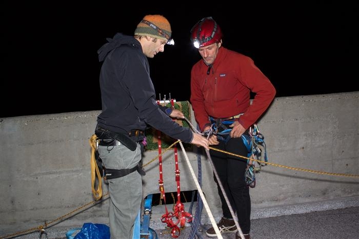
Spectacularly dumb idea to hang that much weight (6 Tons!?) from the top of those walls. Those walls are clearly meant for vertical loads. And a much better option (if you feel you have to do this) was available so I really don't understand what made them choose this particular setup. Anybody with an ounce of structural engineering knowledge would have looped the cables through the drainage ports.
Right now this looks like a Darwin award candidate. They're very lucky that those walls contained enough rebar vertically to withstand this load, it's at the worst possible attachment point and at the worst possible angle (especially for the inner wall).
Edit: looking more closely at the picture it seems as though the cables under tension are actually running through the drainage ports of the back wall, the ropes at the top seem slack or loaded both top and bottom of the opposite so there is in fact mostly compressive load on the front wall and about 50% of sideways load on the opposing wall. Still, that structure was definitely not meant to be loaded like this.
This image best shows how they did it - http://jaccuzzi.ch/photos/700/1758_264_seb_11_.jpg - they looped the ropes over the top of the sides on both sides, suspending the platform directly under the bridge so there shouldn't have been any sideways force.
Still seems a bit stupid to put that much additional load on a 70 year old pedestrian bridge though.
This bridge was most likely not constructed as a pedestrian bridge. What you see in the back probably is the bridge that replaced this one when a one way bridge did not provide enough capacity anymore and the old bridge was re-purposed as a passenger and probably cyclist bridge.
Based on that it was definitely built for higher load than just a few pedestrians.
Edit: The German language Wikipedia article actually confirms this [1]. It states that the bridge was built for a traffic load of 13 tons and that the new bridge was built in 1993 to increase capacity. The old bridge was thoroughly renovated after the new bridge had been constructed. The bridge actually is well documented and is under protection as an architectural landmark. It was exhibited in the MoMA for a long time.
Based on the amount of prep these guys put into this and the available documentation I don't see why they should not have checked if what they wanted to do is possible.
That's weird. It definitely looks like it is the same bridge but that page says it has been removed.
The construction clearly shows a concrete bridge in the making (lots of concrete forms visible) whereas the heading of the page is 'Swiss timber bridges'.
as far as i understand it the timber bridge was the temporary bridge used to support the construction and then torn down after the concrete bridge was completed.
> ...platform directly under the bridge so there shouldn't have been any sideways force.
No net sideways force. Any +X force on the left wall will have a -X force on the right wall. If there's a tension T in the ropes across the top they'll be pulling the walls inward with a force of T causing a torque of T*height.
> If there's a tension T in the ropes across the top they'll be pulling the walls inward with a force of T causing a torque of T*height.
Almost, you'd still have to subtract the friction component across the 90 degree angle where the cable hangs down from the edge near the porthole but that's probably relatively small compared to the total (depends on cable material and any kind of padding they put in between the cable and the concrete).
It would have been a lot better to sling those cables through the portholes on both sides and to make it loop the bridge, one person would have to rappel down to get that started but you'd have zero load on the walls.
The longer I think about this the more I think those guys and girls were extremely lucky and I hope that this will not inspire any copycats to try this with other bridges or even the same one. It's a long way down.
I prefer to live in a frictionless world :) It looks like it was rope on metal (http://jaccuzzi.ch/photos/700/1722_264_03.jpg) with a coef. of friction of 0.2. My gut says the friction force will be at most half horizontal. That puts friction an order of magnitude lower than T, though that is more than I expected. (edit: damn, it rounds the corner from vertical to past horizontal so my symmetry argument doesn't quite hold.)
Why they went over the top of the walls I don't know, I think they wanted to measure the ropes exactly instead of adjusting it the day of. Like, that was where they drew the line of "unacceptable risk"? I agree a loop through the drain holes would have made their lives easier in a bunch of ways, except the tripping hazard would have made it a very risky project...
The bridge is 168.36m long and (I guess) about 2m wide. If there was 1" deep water all the way along that'd be about 10 tons of loading. But that'd be distributed along the entire length of the bridge, not concentrated at a point in the middle...
To be fair those walls were designed to take horizontal wind loads, too. 100mph wind translates to 0.17psi[0] which is ~220 lbs/square yard (of course you assume the force happens halfway up, not at the top of the wall!) If the ropes were spread out over 5 yards then that span should hold ~1500lbs against the face of the wall.
If that thing weighed 6 tons they may have made it out of the "designed to handle" range and into the "safety factor" range of inward forces on those walls. Surely those drainage ports weren't designed to handle upward loads?
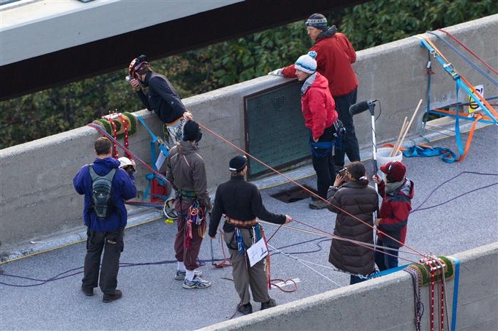
I really can't believe some of them took their harnesses off while in the pool.
Right now this looks like a Darwin award candidate. They're very lucky that those walls contained enough rebar vertically to withstand this load, it's at the worst possible attachment point and at the worst possible angle (especially for the inner wall).
Edit: looking more closely at the picture it seems as though the cables under tension are actually running through the drainage ports of the back wall, the ropes at the top seem slack or loaded both top and bottom of the opposite so there is in fact mostly compressive load on the front wall and about 50% of sideways load on the opposing wall. Still, that structure was definitely not meant to be loaded like this.